🌲🌲 Our Public Lands 🌳🌲
Interactive maps with backcountry and roadside camping: New York , Pennsylvania , West Virginia & Vermont .List of NYS DEC Lean-Tos with map coordinates. List of NYS DEC Firetowers with map coordinates and more information.Roadside, Primitive and Pay Campsites
Explore the Finger Lakes Trail , Long Path , Northville-Placid Trail and Long Trail/Appalachian in Vermont .Catskill Park Mountain Peaks , Hudson Valley & Long Island Peaks , Peaks Over 3000 ft Elevation , Highest Peaks in Adirondacks , Interactive Map of All Named Summits in NYS , Blaze Colors in Catskill Park, Trailhead Parking Coordinates and Addresses in the Catskills .
Browse USGS Topo Quads as PDF 🆕 by State Lands or County. You can Bulk Download New & Old USGS Topograpic Maps .
Links to various NY State Land Websites 🆕. Get latest GIS Data from state Web Services .
⛺🌲 Camp 🌲🏕
Moose River Plains - Campsite Listing, Maps and photos of state's largest free camping area. Piseco-Powley Road - Campsite Listing , Maps and photos of 15 mile dirt road with camping. Catskill Park Primitive Campsites - An overview of free camping locations in Catskill Park. Burnt-Rossman Forest , Cattaraugus County , East Branch Sacandaga River , Finger Lakes National Forest , Madison County , Pennsylvania , Vermont and West Virigina .
Campsite Coordinates for Bog River Flow / Lows Lake , Hudson River SMA (Buttermilk Falls), Lake Lila , Oswegathie River , Nine-Corner Lake , Pharaoh Lake Wilderness , Saranac River Campsites , Stillwater Lake , Schoharie County , and Sugar Hill State Forest .
Overview of Camping Areas in the Catskills , Green Mountains , Southern Adirondacks , Central Adirondacks , Northern Adirondacks , Allegheny National Forest and Penna. DCNR Motorized Campsites and the Monongahela National Forest West Virginia .
Free Campsite Overview Maps: Adirondack - North Country , Catskills, Central NY , Finger Lakes , Western NY. Interactive Map .
Places I camped in 2023 , 2022 , 2021 and 2020 .
Bicycle Trails and "Blackie" My Mountain Bike Finally bought a mountain bike , after chewing over a mountain vs commuter bike . Really enjoying riding my bike to work and when it rains there is always a bike rack to safely take it back home . One way to get to adventures at Thacher Park is the Nature Bus .
Empire Trail - KMZ and Interactive Map. Parking along it .
More Trailways with KMZ files including the Albany County Rail Trail , Black Diamond Trail , Catharine Valley Trail , Catskill Scenic Trail , Fonda, Johnstown & Gloversville Rail Trail , Genesee Valley Trail , Link Trail .
🦌🌲 Hunt 🦃🐿
Wildlife Management Units (Deer) - KMZ Map shows the WMU boundaries.
Summer 2019 Aerial Photographs of WMUs
KMZ Maps of Deer Harvest Density by Town: 2019 , 2018 , 2017 , 2016 . By WMU 2017 , 2016 , 2015 .
KMZ Maps of Buck Harvest Density by Town: 2019 , 2018 , 2017 , 2016 . By WMU 2017 , 2016
2016 -2019 Deer and Buck Harvest by Town - KMZ Spreadsheet with FIPS codes for making your own calculations.
🎣🐡 Fish 🐟🐠
Parking and Access to Trout Streams - An interactive, downloadable KMZ Map. Lakes with DEC Contour Maps - A KMZ Map links to Contour Maps for Fishing.
🌨🏔 Sled & Wheel 🚙❄
State Truck Trails Over A Half Mile - Dirt roads to explore in the backcountry. NYS Statewide Snowmobile Trail System - State trails on public and private lands.
📉📊 Learn 💵📈
Interactive Maps of NY Census - Explore and download KML files. Charts and Interactive Diagrams - From population to pollution control. Andy Arthur GitHub - Git my R and Python scripts used to make maps and diagrams. Use ArcPullR to Get Geospatial Data - Super easy way to connect to get GIS data in R from government servers. GDAL Opens E00 Files - Most open source programs nowadays can open common geospatial formats. NY Building Footprints - Where to find on the internet for making maps. WMS and ArcMap Services - Downloadable CSV file listing services used on the blog. 2022 US Census Population Estimates - Red states, south continue to gain population. 2020 Cartogram of State Population
💳 🏛 Property Taxes 🏠💸
Properties in Albany Pine Bush Study Area , Excel Files: Various Tax Rolls , Find coordinates and political districts , Look Up State Tax Records and a Script for Processing RPTL 1520 PDFs . Match NY SWIS Codes to FIPS Codes and GEOID . How to Find MapServer Data and Load Into QGIS .
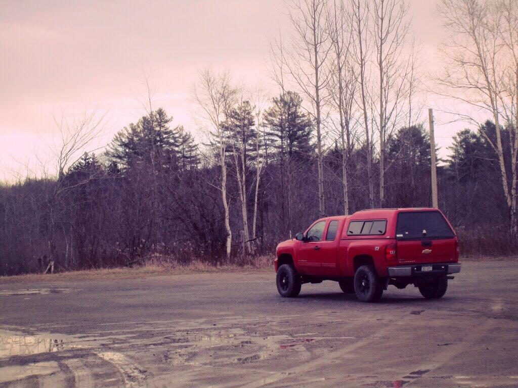
🚗🚗 Big Red 🚗🚗
Big Red - Photos and Videos of my lifted truck with its camper shell. Big Red's Dual Battery Setup for Camp Power ,Video Tour and Diagram . Big Red is getting old. What is next? I've thought about going carless for a while to save money and reduce pollution. Or maybe going bigger ? Or smaller ? Five dollar gas sucks.
🔥🌲 Off-Grid Living 🏠🤠
I am seriously thinking about building an off-grid house. I have a first draft . I need to learn CAD ! I have a road map towards buying land and building . I concede might have to live with long commute and give up traveling and camping . I need to be strong .
Why off grid? Well, I'm not into contemporary society. I want to own land , but not be called a landowner , and a cabin , not hooked to electrical grid , farm , raise pigs for food and burn my own trash . I'm saving for a better tomorrow , hoping to make the leap to another freer state . Having acreage is important . Cornfields aren't bad neighbors . Maybe though my vision has grown smaller and more local. More on off-grid living .
I am 16 years into my career and have made some significant progress in my life. I love my job. But I do wonder on all the things I'm missing out but saving sure makes me high . Maybe it will be different when I own my own land -- the end of goal of all this saving .
2020 into 2021 during the pandemic was a year of remote work . It was a struggle not having internet at home , worked a lot out of my truck. But I worked remotely from Horseshoe Lake which was super cool.
Generally I like the idea of owning land in a red state , particularly Idaho , Iowa , Pennsylvania, West Virginia , Wisconsin -- and Midwest more generally . But I may settle for New York - it's all about the f-ing money!
💻👨💻 Open Source 🗺️📍
I use open source software and public sources of data for the blog. Quantum GIS (QGIS) , GDAL/ogr2ogr , PyQGIS , GeoPANDAS , R Studio and Leaflet for map making, Arduino and ESP32 microprocessors , Ubuntu Linux and XFCE Window Manager . I've recently gotten interested in machine learning.
I avoid using commercial software like Microsoft Windows and do not have home internet or television . If you don't use commercial software and use your brain, fears of computer viruses are overblown . I deleted most of my social media accounts.
Creating Digital Surface Models using LiDAR Point Clouds .
The R programming language and RStudio are powerful tools for statistical analysis, making maps and charts . Many of the blog posts and analysis I do are in R, ggplot not only makes great charts but also maps using tidycensus . Generally, R is better then Python for geospatial work.
Use IDW Interpolation to fill in missing Census data, Zonal Histograms for land cover, load WMS Aerial Photography in R, find mountain peaks , save Census shapefiles using tigris quickly , pull NY Election Night Results using Selenium . Fast reverse Geocoding in PostGIS . Working with PDFs in R . Fix a common error starting rselenium /wdman. Make data-filled calendars. R is wonderful and weird , learn it !
Querying state property database, political enrollments , PL 94-171 Census files , calcula t ing population statistics , what address is a district in , converting old districts to new districts , Shapefiles missing Projection information in QGIS .
Learn to code for free modern HTML, Javascript, Python and SQL at freeCodeCamp and web development at the Odin Project .
Crunched Election Results with Turnout for Albany County: November 2023 , 2022 , 2021 , 2020 , 2019 and Primaries June 2019 , Pres/June 2020 , June 2021 , June 2022 , Aug 2022 , June 2023
Albany County Races converted to the new 2023 EDs using Super EDs and Code : 2022 , 2021, 2020 , 2019 and Primaries June 2019, Pres/June 2020 , June 2021 , June 2022 , Aug 2022 .
Above Election Results as zipped Excel files.
Albany County Legi slature Districts 2024 Maps -
Maps Comparing 2017 and 2023 Albany County Election Districts and a Crosswalk Table Showing the Proposition of Voting Age Population in New and Old EDs
Maps of 2022 NYC Assembly Races , NYS Assembly Races , NY Senate Races , Governor's Race in Erie County and Statewide . Partisan shift in governor race between 2010 and 2018 .
A comparison of Democratic Performance 2022 Assembly Districts to those proposed in 2023 by the IRC. Here is latest 4/20/23 IRC Maps, showing ADP and how they change from existing Assembly districts . Most towns upstate, outside of cities, are quite red . Using LATFOR data with R to calculate Average Democratic Performance.
You can scrape employee salary data from SeeThroughNY using R. Other useful investigative resources .
I often think politics is for losers . I'm into the politics of statistical analysis and reading history books.
I believe strongly in the first amendment , second amendment , oppose gun restrictions and I support de-funding the police Maybe use red flag laws for voting to stop dangerous voters? And the media should stop promoting mass-shootings , even if it's super profitable for all involved. They should tax the media when it promotes violence . I think some people are much too paranoid in politics. How elections are rigged under law to benefit incumbents. But vote , it's the best option and inexpensive .
Yeah for the third parties ! Larry Sharpe for Governor and Jo Jergenson for President but my views are complicated and often vote for Democrats, after voting Jill Stein Green Party in 2016.
Some thoughts on Joe Biden not seeking re-election . Times change, but Biden was been a good change glad the Trump era is over and are glad prosecutors and grand jurors are holding him responsible by indicting him for many serious felonies. I don't think Trump can win in 2024 , as nothing has changed politically from 2020.
I think rural people should be left alone and not worship government workers or have parades for them . I am no fan of Donald Trump , his speeches are bad , I don't like Trump's embrace of radical environmentalists , but do admire the homemade roadside monuments to DJT.
Earth Why I oppose wilderness areas and parks . It's trendy to be green these days, but is eco-marketing good for the planet? I visited the Mount Storm Coal Plant and Corridor H.
I worry about a lot about overly-aggressive Climate Change Action , and Undermining Environment Laws for Climate Action . I think we should all admit we are Addicted to Fossil Fuels . These days, urban recycling has become a joke, when it's still an option at all. It's better to just buy less shit and avoid the alure of Costcos . I really don't like how aging radicals have become industrial solar salespeople.
Big bucks are coming to state-designated disadvantaged communities under the CLCP. Which counties and political districts are in line for the the most pork? Interactive map.
I'm a big of farmers who are essentially Living Off the Earth and think Rednecks are Noble Savages . Dairy Farming are key to our rural landscape. I'd trust a farmer or a hunter in a pile of guts he's butchered over any ivory-tower scientist.
🌎🔆 Industrial Solar 🌞 🏭
Hundreds of multi-acre industrial solar farms are being built in our state. How bad is solar for the environment? We should ask tough questions. Interactive of recently built solar farms , proposed facilities . List of proposed industrial solar facilities . See how the Greenville Solar Farm changed the landscape .
I am not a fan of ESG Investing as it's not well diversified. I prefer index-funds and other tax-advantaged ways of saving . Why I am concerned about saving enough for retirement , even though I'm in my late 30s. We as a nation should save more , consume less. I like the idea of carbon tax to replace capital gains taxes to discourage consumption .
Mission Fifty, Smoking Grass & Being Healthier I am now officially in my 40s ! I am building to a better life in my 50s , which means getting up early , walking a lot , saying no to cake and yes to more fruit . In many ways, the forties are an awesome time to be alive.
And eating healthy for less without losing sleep over arsenic. And I don't think we should subsidize unhealthy habits . How I got started in eating healther too focused on meat and carbs due to how we describe them , maybe I eat too many bananas in the office , what to eat while camping , worry more about salt then GMOs, eat more beans . Do spend extra for farmers market peaches , especially doughnut peaches and plums. Consider ethnic supermarkets. Thinking about how to make a healthier macaroni and cheese , spinach-mackeral-pasta salad , quick-cook biscuits and whole-wheat bread . That said, too many recipes are junk food crap . Okay in moderation is not okay. The fact that I'm thinner is not a sign I'm dying .
A few years back I decided to explore my mental illness with therapy, thinking about why I have so much anxiety and how many of my values are rational or just thinking too much rednecks' burn barrels and how much of a throwaway society we live in . Do I want to change ?
I've learned to care less about the world, and focus more on myself . Maybe I am happier as I am now, saving and investing a lot towards owning my own land, where I don't have to deal with all the bullshit of modern life .
And smoke more grass, now that's legal. Smoking pot is fascinating . Enjoying the rich colors . A map of licensed pot retailers in NYS . Yes, that stuff we used to think of as the smell of crime . Thoughts on Stoner Culture. Not that the blog advertisers like it .
Mission Fifty : Getting to the point where I own my own land. Healthy Eating / Growing My Wealth Healthy Thoughts / Enjoying Life
Questions, comments? Feel free to email me at andy@andyarthur.org .
You do your thing, I'll do mine.I smoke pot and drink cheap beer, up in the wilderness. Yes it's my right !I use GNU open source software. because they're real macho men
I own guns, but not nearly enough. Some day when I live in a pro-2A state ... " I can't make everybody happy, so I'll just be myself." - Andy Arthur Return to the Top
Laugh a bit and learn how your data is used on this blog: Privacy Policy
This blog is © Copyright 1997-2023 Andy Arthur.org , please share using the Creative Commons Attribution 3.0 License.